http://nr8o.dhlpilotcentral.com/?p=83
Like a lot of Hams, while browsing for electronics on eBay I came across some of these super inexpensive DDS modules being sold and shipped from China (less than $6 as of August 2012). That’s cheaper than you can buy the 9850 chip by itself here in the States! Without any research whatsoever I went ahead and added 2 to a recent order of some other components I needed.
About 2 weeks later my package arrived and here’s the board I ended up with.Anyway, I had visions of dragging out the breadboard, hooking up some jumpers, maybe throwing a couple of capacitors in there… As anyone can tell you that’s bought one of these on impulse – it’s a little more complicated than that. There is actually some math involved, bits, bytes, hexadecimal, longwords even. Stuff I hadn’t seen since college (what I remember of college anyway). So, I finally sat down the other day and dug in to what it would take to get this thing going.
Long story short, to get any output from one of these you need to send 40 bits of data to the chip, either via it’s serial or parallel interface. It’s all explained in the official Analog Device datasheet here –
http://www.analog.com/static/imported-f ... AD9850.pdf
I read it the other night to help me fall asleep.
Ahh, just kidding. It’s actually pretty cool stuff. You can interface to the board via your computers serial or parallel port, but as a recent Arduino convert, I decided to go that route. I ended up modifying slightly an Arduino sketch that was written for the 9851, putting the AD9850 on a UNO prototype shield, and testing it in single frequency mode. I can envision using these as a crystal eliminator for some older tube type transmitting gear I have here, maybe controlled with an Atmel 90S2313 or PIC. It’s about comparable in cost to buying an actual crystal for the older gear, and you’re not stuck to one frequency.
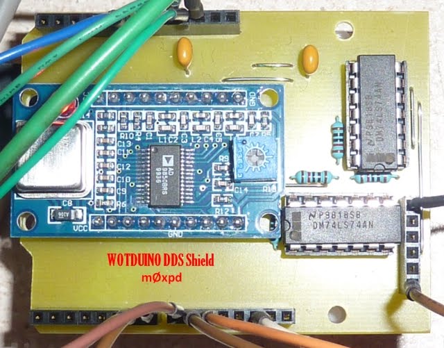
Ok, so here are the two board versions, with pinouts labeled that I’ve seen on eBay.
I used a prototype shield with breadboard, although it’s not necessary. You could just jumper to the main Arduino board.
Using digital pins 8 through 11, proto shield installed on the UNO. Pin 8 to CLK, 9 to FQ, 10 to DATA, and 11 to RST.
Here is the modified sketch for the 9850. Just cut and paste, and upload to your Arduino board. At the very end of the program you can choose which frequency you would like.
代碼: 選擇全部
/*
 * A simple single freq AD9850 Arduino test script
 * Original AD9851 DDS sketch by Andrew Smallbone at www.rocketnumbernine.com
 * Modified for testing the inexpensive AD9850 ebay DDS modules
 * Pictures and pinouts at nr8o.dhlpilotcentral.com
 * 9850 datasheet at http://www.analog.com/static/imported-files/data_sheets/AD9850.pdf
 * Use freely
 */

 #define W_CLK 8       // Pin 8 - connect to AD9850 module word load clock pin (CLK)
 #define FQ_UD 9       // Pin 9 - connect to freq update pin (FQ)
 #define DATA 10       // Pin 10 - connect to serial data load pin (DATA)
 #define RESET 11      // Pin 11 - connect to reset pin (RST).

 #define pulseHigh(pin) {digitalWrite(pin, HIGH); digitalWrite(pin, LOW); }

 // transfers a byte, a bit at a time, LSB first to the 9850 via serial DATA line
void tfr_byte(byte data)
{
  for (int i=0; i<8; i++, data>>=1) {
    digitalWrite(DATA, data & 0x01);
    pulseHigh(W_CLK);   //after each bit sent, CLK is pulsed high
  }
}

 // frequency calc from datasheet page 8 = <sys clock> * <frequency tuning word>/2^32
void sendFrequency(double frequency) {
  int32_t freq = frequency * 4294967295/125000000;  // note 125 MHz clock on 9850
  for (int b=0; b<4; b++, freq>>=8) {
    tfr_byte(freq & 0xFF);
  }
  tfr_byte(0x000);   // Final control byte, all 0 for 9850 chip
  pulseHigh(FQ_UD);  // Done!  Should see output
}

void setup() {
 // configure arduino data pins for output
  pinMode(FQ_UD, OUTPUT);
  pinMode(W_CLK, OUTPUT);
  pinMode(DATA, OUTPUT);
  pinMode(RESET, OUTPUT);

  pulseHigh(RESET);
  pulseHigh(W_CLK);
  pulseHigh(FQ_UD);  // this pulse enables serial mode - Datasheet page 12 figure 10
}

void loop() {
  sendFrequency(10.e6);  // freq
  while(1);
}